Kichler 15317 User Manual
Browse online or download User Manual for Lighting Kichler 15317. Kichler 15317 User Manual
- Page / 2
- Table of contents
- BOOKMARKS
Rated. / 5. Based on customer reviews
SAFETY INSTRUCTIONS
READ THIS FIRST
KEEP THESE INSTRUCTIONS
This xture is intended for installation in accordance with the National
Electric Code (NEC) and Local code specications. Failure to adhere to
these codes and instructions may result in serious injury and/or property
damage and will void the warranty.
1) WARNING: This xture is not to be installed within 10 feet (3M) of a pool,
spa or fountain.
2) This xture is to be used only with a power unit (transformer) rated a maximum
of 300 W (25 AMPS) 15 volts.
3) The #18 ga. xture wire is not intended for direct burial.
4) Direct burial rated wire is to be buried a minimum of 6” (152mm) beneath
the surface of the ground.
NOTE: If additional Direct Burial wire is needed, contact your local
Kichler
®
landscape distributor.
• 8 GA wire can be purchased in length of 250’ (76 M), 15503-BK.
• 10 GA wire can be purchased in length of 250’ (76 M), 15504-BK.
• 12 GA wire can be purchased in lengths of 100’ (30 M), 15501-BK; 250’
(76 M), 15502-BK; 500’ (152M), 15505-BK; and 1000’ (304 M), 15506-BK.
5) Fixture shall not use a tungsten halogen lamp unless the xture is marked
for use with such lamps.
6) Wiring connections must be made with approved/listed wire connection
device(s) suitable for the application. Do not exceed manufacturers’ wiring
combination specications for size and quantity of conductors.
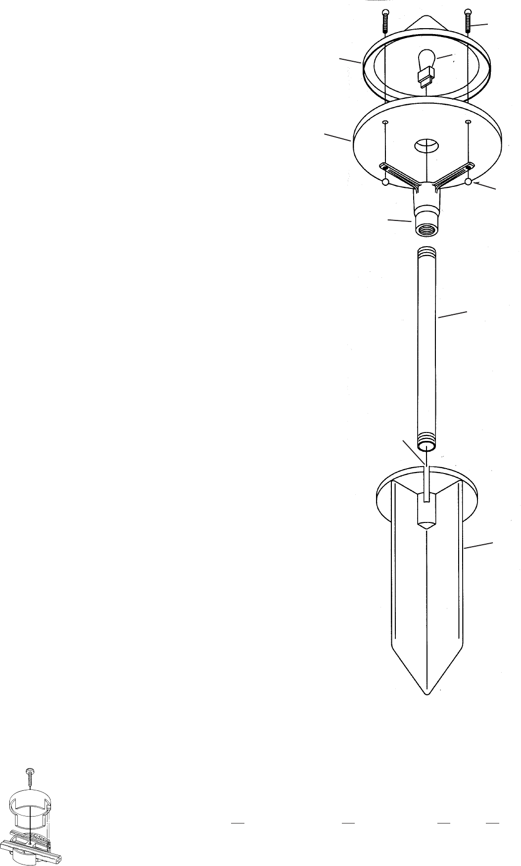
ASSEMBLY AND INSTALLATION
1) Determine desired location for mounting xture.
2) At desired location, hammer stake (A) into ground. To avoid damage to
stake, place a board on top of stake while hammering. If ground is hard
and stake is difcult to install, make a crosscut in ground using a at
shovel.
3) Clear away area in ground at wireway slot (B) in top of stake (A).
4) Run 12V cable from xture body (D) through stem (C).
5) Screw stem (C) into xture body (D).
6) Lay 12V cable into wireway slot (B) and screw stem (C) into stake (A). If
assembly does not look straight, adjust by pushing or pulling on stake only.
7) Install provided lamp (E) to socket inside xture body (D)
8) Slip glass (F) over lamp (E) and align holes in glass with holes in legs on
xture body (D).
9) Lay roof (G) over glass (F) aligning holes in roof with holes in glass and
legs.
10) Slip ball screws (H) through holes in roof (G), glass (F) and legs then
secure together using ball knobs (J). (NOTE: Slip in all three ball screws
before threading on ball knobs. DO NOT OVER TIGHTEN, nger tight is
sufcient.)
11) TURN OFF POWER.
12) Make wire connections using supplied Quic Disc
™
following instructions
below, or using other approved wiring connection method (not supplied.)
Date Issued: 12/2/11 IS-15317-US
For warranty information please visit: http://www.landscapelighting.com/portal/warranty_page
Para informacion de la garantia por favor visite: www.landscapelighting.com/portal/warranty_page
QUIC DISC
™
WIRING INSTRUCTIONS
Turn off power.
The full length of the 18 GA xture wire may be used to connect with the 10 GA or 12 GA cable provided the following conditions are met:
• Wiring is to be protected by routing close to the xture or accessory or secured to a building structure such as house or deck.
• 18 GA xture wiring is to be cut off so that it is attached to the connector within 6 inches of the xture or building structure.
• If it is necessary to make the connections underground, then no more than 6 inches of the 18 GA xture wire is to be buried.
The Quic Disc
™
connector is designed to install one xture and accommodates one 18 GA xture wire and one 10 GA or one 12 GA supply wire.
Place the 10 gauge supply wire across the area marked 10 GA on Quic Disc
™
or place the 12 gauge supply wire across the area marked 12 GA
on Quic Disc
™
.
Place the 18 gauge xture wire across the area marked 18 GA on the Quic Disc
™
. After the wires are in place, connect the top of the Quic Disc
™
to the base with supplied screw, making sure that the wires remain at in the bottom portion of the Quic Disc™, and the screw is tightened all
the way down.
The copper contacts will automatically pierce the wires’ insulation. Excess 18 GA xture wire that sticks out the end of the Quic Disc
™
is to be cut off.
Make no other wiring connections to the 18 GA xture wire.
A
B
F
C
D
E
H
G
J
1
2
Summary of Contents
Page 1 - KEEP THESE INSTRUCTIONS
SAFETY INSTRUCTIONSREAD THIS FIRSTKEEP THESE INSTRUCTIONSThis xture is intended for installation in accordance with the National Electric Code (NEC)
Page 2 - Guarde estas instrucciones
INSTRUCCIONES DE SEGURIDADPrimero lea estoGuarde estas instruccionesEste artefacto se debe instalar de acuerdo con el Código Eléctrico Nacio-nal (NEC,
More documents for Lighting Kichler 15317

Kichler 15317 User Manual
(2 pages)

Kichler 15317 User Manual
(2 pages)
Related products and manuals for Lighting Kichler 15317
Lighting Kichler 15317 User Manual


 (2 pages)
(2 pages)
Lighting Kichler 15382 User Manual
(2 pages)
(2 pages)
Lighting Kichler 3623 User Manual
(1 pages)
(1 pages)
Lighting Kichler 15382 User Manual
 (2 pages)
(2 pages)
Lighting Kichler 15314 User Manual
(2 pages)
(2 pages)
Lighting Kichler 15314 User Manual
(2 pages)
(2 pages)
Lighting Kichler 15314 User Manual
(2 pages)
(2 pages)
Lighting Kichler 15383 User Manual
(2 pages)
(2 pages)
Lighting Kichler 3502 User Manual
(1 pages)
(1 pages)
Lighting Kichler 15383 User Manual
(2 pages)
(2 pages)
Lighting Kichler 3681 User Manual
(1 pages)
(1 pages)
Lighting Kichler 15383 User Manual
(2 pages)
(2 pages)
Lighting Kichler 15165 User Manual
(2 pages)
(2 pages)
Lighting Kichler 3678 User Manual
(1 pages)
(1 pages)
Lighting Kichler 15165 User Manual
(2 pages)
(2 pages)
Lighting Kichler 3606 User Manual
(1 pages)
(1 pages)
Lighting Kichler 3606 User Manual
(1 pages)
(1 pages)
Lighting Kichler 15336 User Manual
(2 pages)
(2 pages)
Lighting Kichler 3743 User Manual
(1 pages)
(1 pages)
Lighting Kichler 3743 User Manual
(1 pages)
(1 pages)
© 2020, manymanuals.com. All rights reserved. | 2.308 s |
 Manymanuals.com
 Manymanuals.de
 Manymanuals.fr
 Manymanuals.it
 Manymanuals.pl
 Manymanuals.cz
 Manymanuals.es
 Manymanuals-pt.com
Comments to this Manuals